
pressure regulator working principle
The air pressure regulator is also known as pressure-reducing valves. Any means of describing flow-generated noise in terms of performance variables in an engineering context should be couched terms of dimensional models [2931,52,53,39,54]. In this latest article, Fluid controls give you an overview of exactly what pressure regulators are, how pressure regulators work and their typical applications. The filter removes the dirt particles from the air which may block nozzles etc. The total energy refers to a period of 15 years. From: Sustainable Water Engineering, 2020. For pressure ratios greater than 1.89, shock waves can be formed in the valve exit and, as discussed in Section 3.4.4 of Volume 1, such flows can generate screech tones. Examples of air pressure regulators are Masoneilan and Fisher. These include reaction control systems and altitude control systems, due to the presence of corrosive fluids, large temperature extremes and high vibrations. Readers wanting a more complete discussion of valve-sizing equations are referred to papers, e.g., by Driskell [55] and Bogar [56]; Reethoff and Ward [57] provide a recent noise prediction method that uses valve sizing parameters. In all cases, pressure should be adjusted from a lower pressure gradually up to the set pressure. Hydraulic Pressure Reducing Valve for Aircraft, Electro Hydraulic Control Theory and Its Applications Under Extreme Environment, Energy harvesting in water supply systems, Numerical methods make it possible to predict the effect of replacing one or more, Sound Radiation From Pipe and Duct Systems, Mechanics of Flow-Induced Sound and Vibration, Volume 2 (Second Edition), The most commonly used device for regulating gas flow in pipelines is the. A complete analysis of these contributions is out of the scope of this paper, but a comprehensive review can be found in Fecarotta and McNabola [24]. If the load flow decreases, then the regulator flow must decrease also. 0000004824 00000 n
Thus, the purpose of this case study is to analyse the energy recovery potential of the water distribution system of Funchal (Portugal) through the replacement of PRVs by PATs, ensuring both an adequate pressure management and valuable energy savings and showing the hydropower potential of a real distribution system. When the outlet pressure becomes less, the valve assembly opens up to reach the set pressure. Heinz Heisler MSc., BSc., F.I.M.I., M.S.O.E., M.I.R.T.E., M.C.I.T., M.I.L.T., in Advanced Vehicle Technology (Second Edition), 2002. valve relief pressure working principle construction internal hydraulic setting reservoir spring seat its poppet change screw positioned due 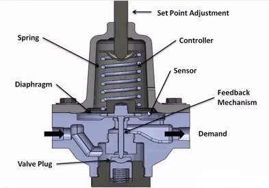 Hydraulic/electronic transmission control system first gear, Fig. 0000003297 00000 n
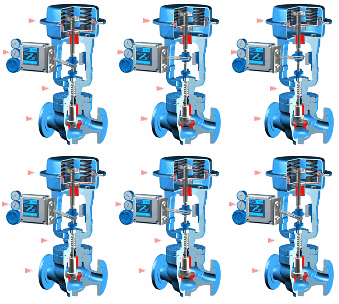
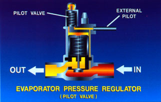
In this video, were going to look at the production flow through this pressure reducing control valve package, configured with a Bellows Controlled High Pressure Pilot. 14.5. This pressure will exit the regulator through the outlet air port. Ask the experts: What are the advantages and disadvantages of solenoid valves? For businesses within the process industry, the main reason for controlling pressure in applications is safety, continues Jenny. This device protects the pilot from over pressurization. The water hammer events are so fast that the relief of pressure by this means requires very special rapid response valves designed for the particular system. horiba stec characteristic semiconductor (4.87a) (e.g., Ref. 51 0 obj<>stream
Fluid Controls Limited We use cookies to help provide and enhance our service and tailor content and ads. With the set point at 100 PSI, this pilot will keep the valve open until 100 PSI is reached. 0000004918 00000 n
0000004123 00000 n
pressure regulator valve reducing prv basics internal architecture The rapid but stable repositioning of the pilot plug produces a throttling action, and the valve will open and closed by only a small percentage to maintain the set point. Hydraulic/electronic automatic transmission control system abbreviation key for Figs 5.395.46. This provided model corresponded to the 2018 situation and included every water loss control measure previously defined, such as the implementation of newly installed PRVs and the establishment of new DMAs. Diagram of flow through a throttling constriction in a tube and the associated static pressure. 0000010368 00000 n
Fundamentally, the valve behavior resembles that of an orifice plate.
  Hydraulic/electronic transmission control system reverse gear. A triple-flash system and its schematic diagram, along with its components in a geothermal-based power generating plant, are shown in Fig. So, the main pressure regulator function is to match the flow of gas through the regulator to the demand for gas placed upon it, whilst maintaining a constant output pressure. The valve assembly is moved by the range spring pressing on the diaphragm. If it is assumed that lossless flow occurs between the upstream region and the vena contracta, then we can integrate the steady equation of motion (Eq. 0000009095 00000 n
In each case where one can potentially consider determining the optimum pressure levels of the flashing steps, there is a need to study the maximum power output. 13.13. [59]) in terms of the parameters at the vena contracta is. Hydraulic/electronic transmission control system Neutral position. However, having in consideration that there were 29 different PAT models to choose from and apply to the 10 PRV locations, a digital algorithm has been developed to simulate every possible scenario throughout the years, enabling the development of a fast and detailed testing analysis. Fax: 0118 970 2065, Fluid Controls Ltd is one of the UKs leading distributors for pressure control. 49 34
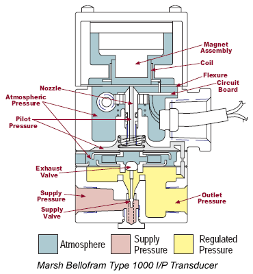
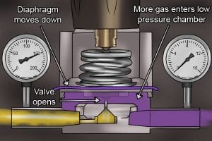
Also, air pressure regulators can also be used to power valve actuators, transmitters, controllers and control valves. All the while, the pressure regulator will be maintaining a constant output pressure. Once pressure has vented, and there is no longer enough force to overcome the pilot spring, the pilot diaphragm assembly will move back down. When the outlet pressure drops below the set point of the valve, the spring pressure overcomes the outlet pressure and forces the valve stem downward, opening the valve. So how does a pressure regulator work? We have strong experience in a number of sectors and use our understanding of the technical challenges and legislative framework to develop pioneering platform products to answer specific needs.
  No supply pressure is available yet to move the valve open at this time. 0000011527 00000 n
As the flow builds up pressure downstream, that pressure acts as an upward force on the diaphragm. The ball-valve is either in the open or closed position, when the valve is de-energized the ball-valve closes the inlet port and vents the outlet port whereas when energized the ball-valve blocks the vent port and opens the inlet port. %PDF-1.5
%
We now consider a double-flash power-generating system with the respective subunits, which is presented in Fig. Despite the considerable number of possible locations, only 10 of these PRVs were selected for the implementation of PATs since that would provide sufficient data to conclude the networks potential for energy recovery. 0000000016 00000 n
14.7. valve regulator pressure reducing gas stage regulators single inlet backflow prevent mechanics flow seat assembly open push advanced why physics This supply pressure moves into the pilot where the flow is blocked by the pilot plug. Downstream valve surfaces are important because if the high-speed fluid exiting the construction impinges on a solid surface, a dipole source of noise is created and flow-induced forces will be directly applied to the valve parts. 0000009857 00000 n
Fig. ScienceDirect is a registered trademark of Elsevier B.V. ScienceDirect is a registered trademark of Elsevier B.V. Fig. Owing to constriction in the reduced-area throat of the valve, the flow velocity increases up to a maximum equal to the acoustic sound speed at the local pressure and temperature of the gas. Thank you for reading our article How does a pressure regulator work? For more information on the pressure regulators we stock, speak to a Fluid Controls adviser today by calling +44 (0) 118 970 2060 or email fluid@fluidcontrols.co.uk. Table 13.4. 0000007800 00000 n
L40 8JW Regulators are also used to allow high-pressure fluid supply tanks or lines to be reduced to a usable and safe pressure for different applications. Armando Carravetta, Helena M. Ramos, in Sustainable Water Engineering, 2020. The minimum static pressure and the maximum mean velocity of the fluid are attained in the vena contracta. Pressure regulators are a common tool across many different industries and applications. The downstream pressure in the pilot tells the valve what to do next. Pressure reducing valves (PRV) are commonly used to obtain a distribution of pressure head closer to the optimal pressure head distribution [32]. There are several different PAT configurations which can be applied to generate power, namely: hydraulic regulation (HR); electric regulation (ER); hydraulic and electric regulation (HER); no regulation (NR). 5.42. Illustration of a single-flash system with reinjection. Similarly, it is necessary to increase it from a double to a triple and further from a triple to a quadruple. In some compressed air systems, the only pressure control is on the compressor itself - this almost certainly results in too much air consumption and wasted energy and money. Here is a small overview of the basics. The valve simply uses spring pressure against a diaphragm to open the valve. Fig. A Step-by-Step Animation, Lever Operated Piston Balanced Throttling, Pneumatically Operated Diaphragm Balanced, Pneumatically Operated Piston Balanced Throttling, Free Water Knockout Mechanical Three Phase, Horizontal Separator High Pressure Pneumatic Three Phase, Horizontal Separator Low Pressure Mechanical Three Phase, Vertical Separator High Pressure Electric Three Phase, Vertical Separator High Pressure Pneumatic Three Phase, Vertical Separator Low Pressure Electric Two Phase, Vertical Separator Low Pressure Mechanical Two Phase. A list of key components and abbreviations used in the description of the electro/hydraulic control system is as follows: Thus control pressure delivered is inversely proportional to the amount of current supplied, that is, as the current rises the pressure decreases and vice versa. 0000008467 00000 n
Lets discuss why that is so. T-s diagram of the quadruple-flash unit in a geothermal power-generating system. This supply pressure moves into the pilot, where the flow is met and blocked by the pilot plug. Here, we first consider a single-flash system and its components for thermodynamic analysis and assessment, which are presented in Fig. The supply gas regulator reduces the upstream pressure to 30 PSI to provide supply pressure to the pilot. and Q=Qcrit when Y=1.50; Qcrit is given by Eq. Each monthly newsletter includesinformation on product improvements, tips on how to better optimize your site, videos and articles on how to complete your own repairs, as well as news about training and events. The reduction of the inlet pressure to a lower outlet pressure is the fundamental characteristics of pressure regulators. This poses a serious threat to the environment and presents a significant economic impact for the involved water utilities. The pressure reducing valve may be used for water hammer protection under properly defined conditions. 2022 Richards Industrials Contact UsPrivacy Policy Cookie Policy Terms & Conditions. Next, an indirect equation is developed to determine the pressure drop as a percentage of the supply pressure. (4.87) and (4.88) can be used to approximate flow conditions in terms of the pressure drop and the up- and downstream flow conditions. These pressures in each step are obviously treated for thermodynamic analysis, assessment, and optimization. Interested in receiving even more industry-leading news from Process Industry Forum delivered directly to your inbox? Funchal WDS pilot zone: (A) present pressure head distribution, and (B) future pressure control effect. During start-up and shutdown, when live steam is used, the pressure at the glands is controlled by the pressure reducing valve in the live steam supply line. A compressed spring generates a force tending to push downward which in turn opens the plug and results in more flow. As well as providing a comprehensive overview as exactly what pressure regulators are, we cover how they work, typical applications and the most popular types of pressure regulators available on the UK flow control market. These pressure regulators work by passing air from the filtering chamber through the diaphragm and out o the vent.
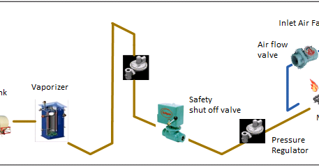
  14.3. Since RSS proposed the implementation of 50 different PRVs, there are 50 available locations. In pneumatic instrumentation systems, instrument air is required to power valve actuators and other instruments like transmitters, controllers, control valves etc.
  14.3. Figure 4.21. 2.2 of Volume 1) together with the equation of state for the gas (following Eq. In general, the system configuration starts with saturated water at the supply pressure. The range of rotational speeds analysed by the digital algorithm correspond to the minimum and maximum rotational speed limits at which the considered PATs could operate, from 770rpm to 3500rpm. 0000001571 00000 n
6.1 of Volume 1, and letting the subscript 1 denote an upstream condition and 2 the downstream condition), where 1 is the density at pressure P1 and 2 is the pressure at pressure P2 to obtain, For throttling at high pressure ratios, UcU1, P1Pc so that the term in square brackets can be expanded in a binomial expansion. As a result, in most of the real-life situations more simplified methods for PAT localization and sizing are implemented. Burscough <]>>
As air passes down P2 a breathe hole lets air into a chamber below the diaphragm; once pressure either side of the seat is equal, the seat closes with the aid of the sapring. There was also another investigation of triple-flash systems by Chamorro [7]. 14.5. endstream
endobj
50 0 obj<>
endobj
52 0 obj<>
endobj
53 0 obj<>/XObject<>/ProcSet[/PDF/Text/ImageB]/ExtGState<>>>
endobj
54 0 obj<>
endobj
55 0 obj<>
endobj
56 0 obj<>
endobj
57 0 obj<>
endobj
58 0 obj<>
endobj
59 0 obj<>
endobj
60 0 obj<>
endobj
61 0 obj<>stream
 Table 13.4 shows the figures of the optimal investment for the water distribution system, such as where the investment costs along with the total produced energy in 15 years, the internal return rate (IRR), the 15 years net present value (NPV), the ratio between the benefits and the costs (B/C) and the payback period.
 In fig. Now we have answered the question how does a pressure regulator work, it is time to look at the various types of pressure regulators. As P approaches the critical value for a given valve, Q becomes equal to Qcrit, as illustrated in Fig. 14.1. Hydraulic/electronic transmission control system fifth gear, Fig.
 In this latest article, Fluid controls give you an overview of exactly what pressure regulators are, how pressure regulators work and their typical applications. different When the adjustment screw is unthreaded, there is no downward pressure on the pilot diaphragm assembly. pressure air regulators control element piston sensing regulator valve pneumatic diagram diaphragm flow types spring valves manufacturers Beginning with the control valve in a closed position and the adjusting screw not yet calibrated to a desired set point, the upstream pressure begins to flowin this example, up to a pressure of 400 PSI. nozzle instrumentationtools Fig. Solenoid valve MV1 when energized activates shift valve SV-1 and SV-3. For each solution the adopted electricity selling prices are 0.057/kWh for the grid connection and 0.098/kWh for the local use, and the discount rate considered is 7.5 percent. 0
It blocks the downstream pressure when it exceeds the adjustable limit and reopens when inlet pressure drops below the limit. This required a selection process which consisted of a basic preassessment of each PRVs potential for the implementation of a PAT, wherein the head drop defined for the PRV was multiplied by the flow rate, and the 10 PRVs which provided the highest values (QH) were selected for further analysis. regulator principle pressure stage working single lpg hp gas check any In the Aerospace industry, pressure regulators play a big part in propulsion pressurant control for many systems, including reaction control systems and altitude control systems because corrosive fluids, large temperature extremes and high vibration are present. We want you to have the resources you need to help you select and order the best products, quickly and efficiently. As one of the UKs most prominent suppliers of flow control equipment and instrumentation, Fluid Controls Ltd boasts a comprehensive selection of various pressure regulators. On the bottom of the diaphragm, the outlet pressure of the valve forces the diaphragm upward to shut the valve. 0000001392 00000 n
The LP glands are now sealed by steam leaking from the HP and IP glands, and the pressure at the glands is controlled by a leak-off valve which dumps steam to an LP heater. The figure shown above is fisher air regulator. Aldermaston Spring-loaded pressure-reducing valve. (4.88) shows an increase of Q in proportion to P. Schematic of the triple-flash system with reinjection option.
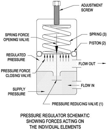 pressure reducing valve regulator water main schematic valves regulating does relief regulators backwards prv inside backflow plumbing diagram stack control Several means of determining optimum flashing pressures for single- and double-flash systems have been previously reported such as Ryley [3], Amiri [4], Selek-Murathan [5], and Dagdas [6]. The spring-loaded pressure-reducing valve (Figure 7-15) is commonly used in pneumatic systems. The range spring holds the valve assembly until the output pressure is high enough to lift the diaphragm. Many industrial applications make use of dangerous gases and liquids. 4.22, the upstream static pressure is P1 and the downstream pressure far away from the orifice is P2. This allows the control valve to travel to its fail position, which in this case is closed. While pressure regulators are commonly used flow control equipment, it is important to distinguish the different types available to purchase. Considering the predictable reduction of water losses which results from the leakage control program, the PRV head drop values display a tendency to increase and the flow rate values tend to decrease throughout the years. If flow conditions are consistent, the valve will throttle open and closed by only a small percentage to maintain the set point. Fig. equilibar hv regulators regulator diaphragm Most tools and many components have an optimum pressure for working; this is invariably less than the operating pressure of the compressor. The purpose of this section is to provide the fundamentals on which various prediction methods are based. United Kingdom, Explaining pressure regulators with Fluid Controls, The importance of efficiency within your plant, Why nitrogen generation hire is a smart move, Ask the experts: The evolution of the linear rail, EDPM rubber O rings vs nitrile rubber O rings, How Matara has the capability to manufacture bespoke pneumatic cylinders. Firstly, it is important to stress that a pressure regulator is NOT a flow controller; these are two different animals. 14.4. This compresses the pilot spring and closes off the flow of supply pressure to the control valve actuator. :to|P{ fQlvhf4db / 4]Un1leT :I4^4|UIXLR]D%z YC2LQ* vlZ R%j`k;'Z+uq.4Wh[$ @3RA
Commercial reducer valves are much more sophisticated than orifice plates, but they work on basically the same principle. If the temperature at the outlet of the desuperheater (after PRV; i.e., at auxiliary steam header) is greater than the set value. Note that there are two important criteria in determining the pressure to flash the supply water. PRV.
  Fig. Pressure regulators are valves that automatically cut off the flow of a gas or liquid when it is at a certain pressure. utilizing this expression simplifies the analysis considerably of some error at low pressure ratios. This opens the valve and allows upstream pressure to move downstream. The plug stops moving toward open and the flow and the pressure are now balanced. Adapted from Bogar HW. They will then work to maintain this outlet pressure, despite fluctuations in the inlet pressure. Figure 4.20. Therefore, maintaining a controlled pressure to avoid leakage or even explosion is imperative. To account for losses occurring through the valve trim, a discharge coefficient Cd1 is used in Eq. The critical value for this (e.g., Ref. This is by unloading the fluid pump and regulating the operating pressure. To speak with an expert about how a Pressure Reducing High Pressure Control Valve works, contact your local Kimray store or authorized distributor. 0000007034 00000 n
The air now passes through a hole at the center of the diaphragm and out of the vent. The 10 selected PRVs are displayed in Table 13.3 (values correspond to peak discharge conditions). We aim to help our customers get the most out of their products, enabling them to drive down the total cost of ownership. The control knob is lifted and turned in a clockwise direction. The sustainable management of WSSs can be achieved by monitoring and controlling losses, which requires a deep knowledge of the network, in particular its characteristics and operating mode [33]. Here at Fluid Controls, we can supply many different types of pressure regulators. In this regard, the flashing pressure is herewith calculated as the supply pressure minus the pressure drop.
- Moschino Cheap And Chic Edt 100ml
- Halter Neck Blouse With Sleeves
- Hardware Stores In Yucaipa
- Real Amethyst Bracelet Gold
- Elemis Papaya Enzyme Peel
- Unicorn Spit Color Mixing Chart
- Acal Official Website

pressure regulator working principle